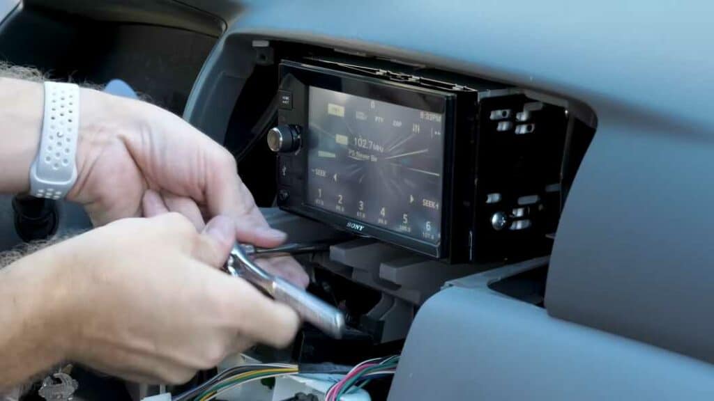
Are you struggling to decipher the complex color codes of a Pioneer wiring harness for your audio system? With 10 years of expertise in car audio installation and maintenance, we’ve mastered the nuances of the Pioneer Wiring Harness Color Code and Wiring Diagrams.
In this blog, we’re outlining the exact steps you need to follow for a hassle-free and accurate installation of your Pioneer system for all types of models, ensuring you get the best performance without the confusion and guesswork
Understanding the Pioneer Wiring Harness Color for DEH and MVH Models
When installing a Pioneer receiver, specifically those starting with DEH and MVH, it’s crucial to know the purpose of each wire in the harness. These models don’t have video screens, and their wire color codes play a vital role in ensuring the receiver functions correctly. Here’s a simplified guide to each wire color and its function:
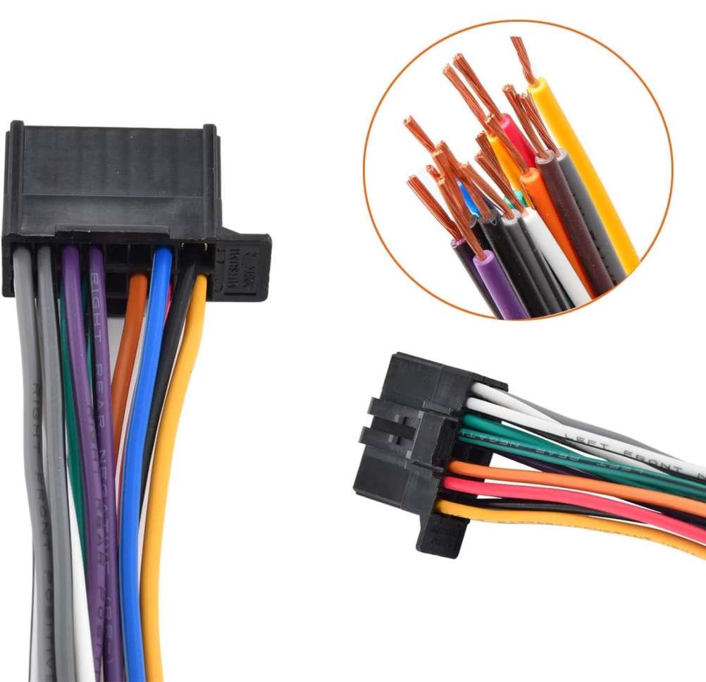
Yellow Wire – Memory Keeper
This wire is in charge of maintaining your settings, like the clock and preset radio stations. It should be connected to a power source that remains active even when the car is off, ensuring your settings aren’t lost each time you start your vehicle.
Red Wire – Power Control
This wire connects to your car’s ignition. It ensures that your audio system powers up only when the car is turned on, helping to prevent battery drain when the car is off.
Orange Wire with White Stripe – Illumination Adjuster
This wire helps dim your car stereo’s display in response to the headlights being turned on, which is especially useful for night driving. However, if your car doesn’t support this feature, or if you prefer constant illumination, this wire can be left disconnected.
Black Wire – Ground Connection
This is your stereo’s ground wire. A solid ground connection is essential for the system to function properly. Typically, it’s connected to the metal body of the car.
Blue Wire with White Stripe – Accessory Power
This isn’t for the remote control of the stereo. Instead, it’s used to power up external components like amplifiers or powered antennas, synchronizing their power state with the stereo.
Speaker Wires – Audio Outputs
These are usually in pairs with matching colors, one solid and one with a black stripe. Each pair corresponds to a different speaker location in your vehicle:
- White Pair: Left front speaker
- Gray Pair: Right front speaker
- Green Pair: Left rear speaker
- Purple Pair: Right rear speaker
The solid-colored wire is the positive lead, and the one with the black stripe is negative.
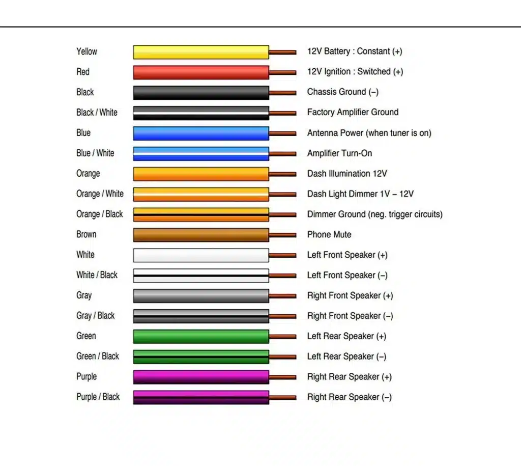
Understanding the wire harness color codes for Pioneer AVH-X models
- Yellow Wire: This is your memory wire. It keeps settings like your clock, radio station presets, and audio settings intact. If these settings reset each time you start your car, check this wire’s connection. It should always have a constant 12V power supply, regardless of your vehicle’s ignition state.
- Red Wire: The red wire connects to your vehicle’s ignition. It should only show 12V when the vehicle is on. This wire essentially powers the system when you start your car.
- Orange and White Wire: This wire controls the dimming of your receiver’s screen when the headlights are on. Not every vehicle has a connection for this wire. Also, if you prefer not to dim your receiver’s screen during the day, even with headlights on, many Pioneer models offer an alternative dimmer setting based on the time of day.
- Black Wire: This is your ground wire. A proper ground connection, usually to the vehicle’s frame or body, is essential for the receiver to operate.
- Purple and White Wire: This wire is used for connecting to a backup camera. It helps the receiver identify when the vehicle is in reverse. If you’re not using a backup camera, cap this wire properly.
- Yellow and Black Wire: It’s a mute control wire, used for integrating with external systems like vehicle communication systems. It’s not commonly used in every installation, so if not in use, cap it safely.
- Blue and White Wire: This wire is crucial for external amplifiers or power antennas. It ensures these devices turn on/off with the receiver. If you’re not using external amplifiers or similar devices, cap this wire as well.
- Light Green Wire: Connected to the parking brake switch, this wire is necessary for enabling video playback on your receiver. Without this connection, video functions and certain menu options will be disabled.
- Speaker Leads: These include pairs of wires (white, gray, green, purple) each with a solid and striped version. Solid is positive; striped is negative. They correspond to different speakers (front left, front right, rear left, rear right) and vary depending on whether you’re using standard or network mode.
16-Pin Pioneer wiring harness color code
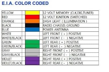
Pioneer Head Unit Wiring Diagram
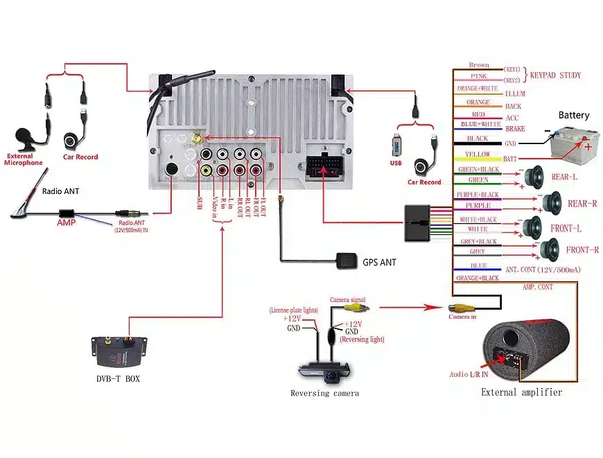
FAQs
What color is the ground wire on a Pioneer radio?
The ground wire on a Pioneer radio is typically black. However, it’s always best to double-check the specific color for your model using the installation manual or a wiring harness diagram.
Here’s why relying solely on the general rule of thumb might not be the safest bet:
- Pioneer uses different color codes for different models and series. While black is the most common ground wire color for Pioneer radios, there have been instances where other colors like brown or gray were used.
- Aftermarket wiring harnesses may have different color codes. If you’re using a wiring harness to connect your Pioneer radio to a non-Pioneer car stereo system, the ground wire color might not be black.
To be on the safe side, always refer to the specific resources for your Pioneer radio model. Here are some ways to find the correct ground wire color:
- Consult the installation manual: The manual will have a detailed wiring diagram that shows the color code for each wire.
- Download the wiring diagram from Pioneer’s website: Pioneer offers wiring diagrams for most of their car stereo models on their website. You can find the diagram by searching for your model number.
- Look for a label on the wiring harness: Some wiring harnesses have labels that identify the color of each wire.
Once you’ve identified the correct ground wire color, be sure to connect it to the black ground wire in your car’s electrical system. Connecting the ground wire incorrectly can damage your radio or even cause a fire.
What is the pink wire on a Pioneer car stereo?
On a Pioneer car stereo, the pink wire serves a specific purpose, but it’s not always required and its function can vary depending on the model. Here’s the breakdown:
Function: The pink wire typically acts as the Car Speed Signal Input. This sends your car’s speed information to the stereo, enabling features like:
- Automatic volume adjustment: As your car speeds up, the stereo can automatically increase the volume to compensate for road noise.
- Navigation system: GPS-equipped models use the speed signal to calculate accurate travel times and distances.
- Mute audio during alerts: Some advanced systems can mute audio for important warnings based on speed, like approaching speed cameras.
Important Details:
- Optional Connection: Connecting the pink wire is not necessary for basic stereo operation. It only becomes relevant if your Pioneer model possesses the features mentioned above.
- Model-Specific: Pioneer uses different wiring conventions across various models and series. The pink wire function can vary, sometimes associated with reverse gear input or other purposes.
- Matching Up: To correctly connect the pink wire, you’ll need to identify the corresponding speed pulse wire in your car’s electrical system. Consulting the car’s manual or a professional installer is recommended.
What is the orange wire on a Pioneer car stereo?
The orange wire often plays a part in illumination control. This means it affects how bright your stereo’s display and buttons are. But the exact role can vary:
- Illumination: In many Pioneer models, the orange wire is the illumination wire. Connecting it to the car’s dimmer circuit allows the stereo’s brightness to dim along with your dashboard lights.
- Dimmer Control: Some models, especially older ones, use the orange wire for manual dimmer control. This means you can adjust the stereo’s brightness directly from its own dimmer knob.
Is orange wire positive or negative?
If the orange wire is for illumination, it typically connects to the car’s dimmer circuit. This circuit is positive 12 volts when headlights are on and grounded or switched negative when turned off. So, the orange wire itself can be considered both positive and negative depending on the state of the headlights.
Purchase Links:
- For DEH AVH AVIC MVH FH SPH
- Toyota and Subaru
- 1998-2005 Ford Vehicles
- 16 Pin Wiring Receiver Harness
Related Post – Aftermarket Car Stereo Wire Colors Guide